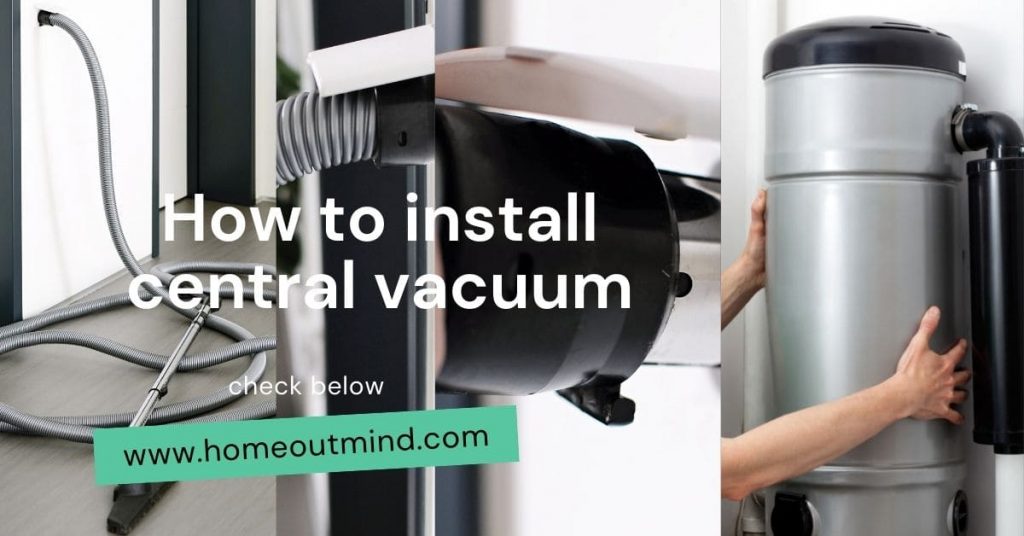
Ditch the noisy, cord-tangled dance: Upgrade to a central vacuum! Imagine effortless cleaning, reaching every nook, and breathing cleaner air.
This isn’t a dream, it’s the reality of owning a central vacuum. No more lugging, straining, or dust clouds.
Ready to unlock convenience and healthier living? Join us as we explore installing your own central vacuum – say goodbye to traditional cleaning woes!

Types of Central Vacuum systems
Before we dive in, let’s pick the right system for your needs.
1. Cyclonic Warriors: These champions use centrifugal force to separate dust, offering powerful suction and minimal maintenance. Ideal for larger homes with pets or allergies. However, they might require an external exhaust.
2. Bagged Battlers: These classic options offer simple disposal but require regular bag replacements. Perfect for smaller homes or those who prefer traditional convenience.
3. Hybrid Heroes: Combining cyclonic and bag technology, these offer strong suction with easy disposal. A versatile choice for various needs.
Layout and placement for the central vacuum
Now, let’s map your cleaning haven. Inlet placement is key – consider high-traffic areas, corners, and different floors.
For the power unit, choose a central, accessible location with proper ventilation. Remember exhaust options – vented outside removes allergens, while recirculating systems require HEPA filters.
Gathering Your Arsenal
To conquer the installation, here’s your battle gear:
- Drill and saw: For creating inlet holes and running tubing.
- Pliers and screwdrivers: For assembly and connections.
- Tubing cutters and fittings: Ensure proper connections.
- Safety gear: Protect yourself with goggles, gloves, and a dust mask.
Remember, consulting a professional for complex layouts or electrical connections is always wise. Next, we’ll conquer the installation journey itself!
A Guide to Central Vacuum Installation (Step-by-Step Guide)
Phase 1: Drilling and cutting
Before breaking out the tools, map your central vacuum haven. Here’s how:
1. Chart the Course: Sketch the tubing path, marking inlet locations and ensuring ample clearance for walls, ceilings, and obstacles. Think traffic patterns and accessibility for optimal cleaning convenience.
2. Safety First: Always wear protective gear (goggles, gloves, dust mask) and prioritize safety. Double-check for electrical wires and plumbing before drilling or cutting anything.
3. Precision is Key: Carefully measure and mark before drilling holes for inlets and tubing access points. Remember, “measure twice, cut once” is your mantra here!
Phase 2: Connecting tubes and valves
Once your plan is set, it’s time to assemble the network. Keep these guidelines in mind:
1. Consult the Mastermind: Each system has its own connection methods. Refer to the manufacturer’s manual for the specific fittings and adhesives recommended for your model.
2. Seal the Deal: Ensure all joints are airtight and secure to prevent leaks that could hinder suction power. Remember, even small gaps can be troublemakers!
3. Label for Clarity: Mark each line clearly with its designated purpose (kitchen, living room, etc.). This will simplify troubleshooting and future maintenance for you and anyone else using the system.
Phase 3: Electrical connection
Remember, safety is paramount! For the electrical connection of the power unit and ensuring compliance with all electrical codes, consulting a licensed electrician is crucial. This is not a DIY step!
Phase 4: Testing and Troubleshooting
After installation is complete, it’s time to put your system to the test. Here’s how:
1. Follow the Master’s Lead: Refer to the manufacturer’s guide for safe testing procedures to assess airflow and identify any potential issues. Pay attention to suction power and listen for unusual noises.
2. Address Blockages: If you encounter leaks or blockages, don’t hesitate to tackle them before regular use. Refer to the manual for troubleshooting tips or seek professional assistance if needed.
Remember: While this guide provides a general overview, prioritizing safety means knowing when to seek professional help, especially for electrical work and code-compliant tasks.
A licensed electrician can ensure the safe and efficient operation of your central vacuum system, giving you peace of mind and optimal cleaning power.
By following these guidelines and seeking professional assistance when needed, you can transform your home with a powerful and convenient central vacuum system, leaving you with more time to enjoy a cleaner and healthier environment.
Maintaining Your Central Vacuum
Now that your central vacuum is conquering dirt and dust bunnies, let’s ensure it remains a champion for years to come. Here are some key maintenance tips:
Regular Cleaning:
Empty the canister or replace the bag: Follow the manufacturer’s recommendations for frequency, usually every 2-3 months or when the indicator shows fullness. Don’t wait until it’s overflowing!
Clean inlet valves: Debris can accumulate around the valves, reducing suction. Remove and clean them according to the manual, typically every 6 months.
Wipe down inlets: Use a damp cloth to remove dust and debris from the inlet covers.
Filter Replacement:
Know your filters: Your system may have multiple filters, each with its own replacement schedule. Consult the manual for specific cleaning or replacement intervals.
Clean reusable filters: Wash them according to the manufacturer’s instructions, usually every 2-3 months. Let them dry completely before reinstalling.
Replace disposable filters: Replace them at the recommended intervals (usually every 3-6 months) to maintain optimal performance.
General Maintenance:
Check the hoses: Inspect hoses for cracks, tears, or blockages every few months. Replace them if damaged.
Keep it cool: Ensure proper ventilation around the power unit to prevent overheating.
Consult the manual: Refer to the manufacturer’s manual for specific maintenance instructions for your system.
Bonus Tip: Schedule a professional inspection every 2-3 years for a thorough cleaning and performance check. This can help identify potential issues early on and extend the lifespan of your system.
By following these simple maintenance steps, you can ensure your central vacuum continues to provide powerful cleaning performance for years to come.
Remember, a little preventive care goes a long way in keeping your home clean and your investment protected!
Is a central vacuum worth the cost?
The cost of a central vacuum system can range from $2,000 to $10,000 depending on size, features, and installation complexity.
While an initial investment, central vacuums offer several long-term benefits that make them worthwhile for many homeowners:
Increased home value: Central vacuums are considered a desirable home upgrade, potentially increasing your property value by up to 5%.
Energy efficiency: Compared to traditional vacuums, central systems use less energy to achieve the same cleaning power.
Reduced noise: The power unit is located away from living areas, making them significantly quieter than traditional vacuums.
Improved air quality: Central vacuums effectively remove dust, allergens, and pet dander from the home, contributing to a healthier environment.
Convenience and ease of use: No more lugging around heavy vacuums or struggling with tangled cords. Simply connect the hose and clean!
How difficult is it to install a central vacuum system yourself?
The complexity of installation depends on your DIY skills and the layout of your home. While basic systems may be manageable for experienced DIYers, most homeowners find it advantageous to hire a professional installer:
Ensuring proper code compliance: Electrical work and certain aspects of installation require adherence to building codes, which a professional can guarantee.
Avoiding costly mistakes: Improper installation can lead to leaks, clogs, and reduced performance. Professionals have the expertise to avoid these issues.
Warranty considerations: Some manufacturers require professional installation to maintain warranty coverage.
How often do I need to maintain my central vacuum system?
Regular maintenance is key to keeping your central vacuum operating at peak performance. Here’s a basic guide:
Empty the canister or replace the bag: Frequency depends on usage, typically every 2-3 months.
Clean inlet valves: Every 6 months to remove debris that can reduce suction.
Wipe down inlets: As needed to remove dust and debris.
Change filters: Follow the manufacturer’s recommendations for cleaning or replacing reusable and disposable filters.
Inspect hoses: Every few months for cracks, tears, or blockages.
Schedule professional inspection: Every 2-3 years for a thorough cleaning and performance check.
Can I install a central vacuum system in an existing home?
Absolutely! While installing in a new construction is simpler, existing homes can also be retrofitted with central vacuums. The complexity depends on your home’s layout and desired number of inlets.
Consult a professional installer to assess feasibility and discuss options like running tubing through basements, attics, or crawl spaces.
Do central vacuums work well on all types of flooring?
Yes! Central vacuums are designed to effectively clean carpets, hardwood floors, tile, and even upholstery. Most systems come with a variety of attachments, allowing you to adjust suction power and brush types for optimal cleaning on different surfaces.
Do central vacuums require venting to the outside?
Some systems do, while others have HEPA filters that allow for recirculated air. Venting outside removes allergens and dust more effectively but requires additional installation considerations. Discuss venting options with a professional based on your needs and local building codes.
Are central vacuums noisy?
The power unit, typically located in a garage or basement, generates noise during operation.
However, it’s much quieter than traditional vacuums since the majority of the system is hidden within walls. You’ll hear only a gentle whoosh of suction at the hose inlet.
How long does a central vacuum system last?
With proper care and maintenance, a central vacuum system can last for 15-20 years or even longer.
Regular filter cleaning, emptying canisters or bags, and professional inspections ensure optimal performance and lifespan.
Conclusion
Ditch the cord dance, breathe easier, clean smarter! Uncover the world of central vacuums – powerful suction, hidden convenience, cleaner air in every corner.
No more lugging, straining, or dust clouds. Imagine effortless cleaning, healthier living, and a home value boost. Start planning your haven – the power of a central vacuum awaits!


